Product Specification
Product | Solar Medium Intensity Light Type A |
Code | |
Version | V1.0 |
Date | 2022/07/26 |
Designed by | Checked by | Approved by |
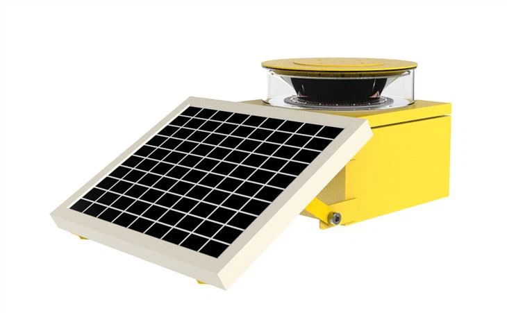
The solar medium intensity type A light is mainly composed of 65mm plastic lens, flasher, battery box and base made of industrial pc (or stainless steel), maintenance-free battery, silicon solar physical panel, etc.
Solar intelligent high-altitude obstacle lamps are mainly used in high-rise buildings, electric power towers, radio and television and microwave communication towers, tall chimneys, bridge towers, exploration wells, ship navigation and airstrips, etc., as signs flashing lights in places that lack power and require explosion-proof.
The 65mm plastic lens is a Fresnel principle lens molded from polyacrylic plastic. The lens has the advantages of high light transmittance and resistance to sunlight aging. The flasher mainly uses high-quality electronic components to form a light-controlled automatic switch, etc., controlled by The ultra-long life LED flashes composed of imported chips, the life of the LED light source can be as long as twenty years. High-efficiency silicon solar physical panels and large-capacity maintenance-free storage batteries provide long-lasting power energy for the flasher, ensuring normal flashing within 20 days of continuous rain.
Solar energy intelligent high-altitude obstacle lamps generally do not require any maintenance for 3 years under normal use.
THE DIFFERENT PRODUCT APPLICATIONS
Rules concerning solar obstruction lights(aircraft beacons) are established by the ICAO (Annex 14, Chapter 6). Our Medium Intensity Lights are all certified and homologated by the International Civil Aviation Organization (ICAO) and can be installed on every obstacle between 45 and 150M of height (Pylons, Civil Engineering Structures, Buildings, Cranes, and Chimneys).
For obstacles that tall it is recommended to plan an illumination on various levels, with Medium Intensity Light at the top, and Low Intensity Light Type B at the intermediate level.
Also, according to the rules, an uninterruptible power supply cabinet has to be installed to insure a 12-hour beacon in case of power supply failure.
1 Technical Parameters
1.1 Dimensions (mm)
1.2 Technical Parameters
The following parameters are obtained under normal temperature test. (25℃)
Item of Test | Parameters | ||
Model | FL-L865S(L) | ||
Structure Parameter | Nominal Dimension | 566.5×434.5×650mm | |
Installation Dimension | SEE BELOW | ||
Material of Lamp Panel | Aluminum Die Casting | ||
Material of Cover | PC | ||
Electrical Parameter | Rated Power | ≤20W | |
Optical Parameter | Light intensity | Background brightness | Light intensity |
>500cd/㎡ | 20000±25% | ||
50~500 cd/㎡ | 2000±25% | ||
<50 cd/㎡ | 2000±25% | ||
Light source | LED | ||
Light color | White | ||
Operating mode | Operating mode | 20-40 flashes/min(adjustable) | |
Function | Aviation obstruction light belongs to airfield ground light product, this product is solar Medium intensity obstruction light type A,it is widely used in airfield clearance zone, airfield course sector, power tower and obstructions more than 60m, can assist pilots to visualize the physical size of the obstruction, to ensure safety flight. | ||
Other Parameter | Operating tem. | -40~+55℃ | |
Solar panel | Custom(20w,30w,etc.) | ||
Battery | Custom(Li battery, LIFEPO4 battery, etc.) | ||
Wind load① | 60m/s | ||
Protection | IP66 | ||
Weight | 4.5Kg(Not include solar panel and battery) | ||
2. Characteristics of Lamp
Our Medium Intensity Aircraft Warning Lights range is composed of 5 versions:
Type A white flashing (20 000 Cd in day mode, and 2 000 Cd in night mode)
Type B red flashing (2 000 Cd in night mode)
Type C red steady burning (2 000 Cd in night mode)
Type A&B white flashing (20 000 Cd in day mode) and red flashing (2 000 Cd in night mode)
Type A&C white flashing (20 000 Cd in day mode) and red steady burning (2 000 Cd in night mode)
Our Medium Intensity Lights are functioning with Led Technology.
That technology allows us to develop sturdier, watertight (IP66) and very low-consuming lights with a long lifetime (100 000 hours).
Our products also benefit from integrating important options such as the photocell when a nocturnal lighting is needed, and the dry contact.
And for a complete solution, Delta Box offers Power Supply Cabinets, Uninterruptible Power Supplies (UPS) and Solar Power Supplies.
This white flashing solar medium intensity type A is widely used in tall buildings, iron towers, large bridges, cranes, chimneys, lighthouses, high voltage transmission towers, drill platforms, etc.
According to regulations from the Federal Aviation Administration (FAA) and the International Civil Aviation Organization (ICAO), any structure that exceeds 45m above ground level is required to be properly marked with aviation obstruction lights. Tall structures like towers, industrial chimneys & smokestacks, and even wind turbines will need to adhere to minimum requirements in order to meet safety regulations.
The height of the structure is only one factor that must be considered when choosing how to place aviation warning lights. Structure diameter, weather, terrain, proximity to airports, and other considerations will ultimately determine the required obstruction lighting setup.
Industrial Access can help establish the proper aviation obstruction light configuration to keep you up to code and within regulations. These warning systems require special attention as regulations continue to evolve. Since requirements may vary depending on your location, the type of structure, and environmental concerns, it’s best to consult with a professional that has specific knowledge of regulation & installation requirements.
Flylight’s R&D team of highly trained rope access technicians can quickly & efficiently install, maintain, and repair aviation obstruction lights on your tall structures or industrial chimneys. Contact us today so we can assess your high angle needs.
3. Installation
3.1 Schematic Diagram
3.2 Instruction
The solar medium intensity type A obstruction light installation instruction manual provides detailed instructions for the installation and use of solar aviation obstruction lights. When installing the obstruction light on site, read the instruction manual carefully to avoid malfunction of the obstruction light due to improper operation.
• Installation instructions:
• The installation and distribution of the product must comply with the relevant requirements for lighting of objects in "ICAO Annex XIV" 6.3;
• This installation manual is applicable to the installation and operation specifications of lamps and lanterns in the iron tower project;
• Before installation, please check the packing list and check the equipment and accessories. If you find that the equipment or accessories are wrong, missing or abnormal, please contact the seller or our company.
• Material preparation:
1. Material requirements:
a) Lamps: The lamps have no mechanical damage, deformation, peeling paint, cracked lampshades and other undesirable phenomena;
b) Mounting bracket for lamps and lanterns: The material is stainless steel, and the mounting bracket is specifically designed according to the tower model (the mounting bracket of the corresponding specification must be selected according to the tower model during installation);
c) Other supporting materials: bolts, nuts, washers, and spring washers, etc.
2. Operating tools:
Spirit level, protective gloves, safety rope, adjustable spanner, rag, electrician's tool bag (including electrician's tool), etc.
• Installation
1. Operating environment: high-altitude tower operation
2. Installation process: lamp inspection → accessories, tools, safety equipment inspection → tower climbing → lamp installation → power-on trial operation
2.1 Lamp inspection:
a. Check the integrity of the lamps;
b. Check whether the mounting bracket of the lamp is consistent with the tower shape;
c. Power-on test. (Press the self-locking switch, the lamp can be powered on and work normally, bounce off and stop working. To prevent accidents during transportation, causing damage to the lamp)
2.2 Inspection of accessories, tools and safety equipment:
Confirm that the installation screw accessories, installation tools and climbing protective equipment are complete;
Check the configuration screws of the corresponding tower according to the following configuration table.
2.3 Climbing the tower: Wear safety protective equipment for high-altitude operations and pay attention to safety.
2.4 Lamp installation
2.4.1 The connection between the luminaire and the mounting bracket is tight:
4. Maintenance
4.1 Keep the lamp in a dry and clean working environment;
4.2 Keep the lamp away from hazardous environment;
5. Standard
All kinds of aviation obstruction lights should be ICAO(International Civil Aviation Organization) or FAA(Federal Aviation Administration) compliant. ICAO FAA both have a standard regarding all kinds of aviation obstruction lights, all lights should be designed and installed according to ICAO or FAA standard. In China, the standard is called “CAAC”(Civil Aviation Administration of China). All kinds of aviation obstruction lights should be compliant with CAAC when they are sold.
5.1 Solar Medium intensity light type A, International Civil Aviation Organization, annex 14, volume 1, 7th edition, “airport design and operation”, July 2016, table 6.3.

Backgroud knowledge:
Aviation obstruction light scheme design:
The aviation obstruction light program is designed according to the height of installation, and the aviation obstruction lights selected for different heights are also different. The aviation obstruction light scheme is divided by 3 height points.
1. Fixed objects less than 45m above the ground in the surrounding area;
2. Objects 45m above the ground in the surrounding area but less than 150m;
3. Objects 150m above the ground or surrounding ground level.
The above three heights require different aviation obstruction light schemes, and the specific setting schemes are as follows:
1. A fixed object less than 45 m above the ground in the surrounding area
Objects that are not too large and are less than 45 m above the surrounding ground should be marked with A-type or B-type low-intensity obstruction lights.
Where the use of Type A or Type B low-intensity obstruction lights may be insufficient or require special warnings in advance, medium-intensity or high-intensity obstruction lights should be used.
B-type low-intensity obstruction lights should be used alone or in combination with B-type medium-intensity obstruction lights.
Large areas of objects should be marked with A-type, B-type or C-type medium-intensity obstruction lights. Type A and Type C medium-intensity obstruction lights should be used alone, while Type B medium-intensity obstruction lights should be used alone or in combination with Type B low-intensity obstruction lights.
Note: A group of buildings are regarded as objects with a large area.
2. Objects 45 m above the ground but less than 150 m above the ground in the surrounding area
Use A-type, B-type or C-type medium-intensity obstruction lights for light indication. Type A and Type C medium-intensity obstruction lights should be used alone, while Type B medium-intensity obstruction lights should be used alone or in combination with Type B low-intensity obstruction lights.
When the top of the obstacle marked by the A-type medium intensity obstruction light is higher than the surrounding ground by more than 105m or higher than the top elevation of the nearby buildings (when the obstacle to be marked is surrounded by multiple buildings), Obstacle lights should be added in the middle. The additional mid-level obstruction lights should be installed as far as possible between the top obstruction lights and the ground or the top elevation of nearby buildings at an equal distance of no more than 105 m.
When the top of the obstacle marked by the B-type medium-intensity obstruction light is more than 45m higher than the surrounding ground or more than 45m higher than the top elevation of the nearby building (when the obstacle to be marked is surrounded by multiple buildings) , An obstruction light should be added in the middle. The additional mid-level obstruction lights should be alternate B-type low-intensity obstruction lights and B-type medium-intensity obstruction lights, and as far as possible between the top obstruction lights and the ground or the top elevation of nearby buildings not greater than 52 The equidistant setting of m.
When the top of the obstacle marked by the C-type medium-intensity obstruction light is 45 m higher than the surrounding ground or 45 m higher than the top elevation of the nearby building (when the obstacle to be marked is surrounded by multiple buildings), it shall be Add obstruction lights in the middle. The additional mid-level obstruction lights should be installed as far as possible between the top obstruction lights and the ground or the top elevation of nearby buildings at an equal distance of no more than 52 m.
Where A-type high-intensity obstruction lights are used, the obstruction lights should be installed evenly between the ground and the prescribed top obstruction lights at an interval of no more than 105 m, but when the object to be marked is surrounded by multiple buildings, The top elevation of nearby buildings can be used instead of the ground to determine the number of floors where obstruction lights should be installed.
3. Objects 150 m above the ground or surrounding ground level
The navigation research shows that objects that are higher than 150 m above the surrounding ground can only be distinguished by high-intensity obstruction lights during the day, and A-type high-intensity obstruction lights shall be used for identification.
Where A-type high-intensity obstruction lights are used, the obstruction lights should be installed evenly between the ground and the prescribed top obstruction lights at an interval of no more than 105 m, but when the object to be marked is surrounded by multiple buildings, The top elevation of nearby buildings can be used instead of the ground to determine the number of floors where obstruction lights should be installed.
If the relevant authority believes that the use of A-type high-intensity obstruction lights at night may cause dazzling of drivers near the airport (within a radius of about 10 km) or cause major problems affecting the environment, the C-type medium-intensity obstruction lights should be used alone. The B-type medium-intensity obstruction light should be used alone or in combination with the B-type low-intensity obstruction light.
When using A-type medium-intensity obstruction lights to mark obstacles, an obstruction light should be added in the middle. The additional mid-level obstruction lights should be installed as far as possible between the top obstruction lights and the ground or the top elevation of nearby buildings at an equal distance of no more than 105 m.
When the obstacle is marked by the B-type medium intensity obstruction light, an obstruction light should be added in the middle. The additional mid-level obstruction lights shall be B-type low-intensity obstruction lights and B-type medium-intensity obstruction lights alternately emitting, and as appropriate, the height of the top obstruction light and the ground or the top elevation of nearby buildings shall be no more than 52m as far as possible. Equidistant settings.
When the C-type medium intensity obstruction light is used to mark obstacles, an obstruction light should be added in the middle. The additional mid-level obstruction lights should be installed as far as possible between the top obstruction lights and the ground or the top elevation of nearby buildings at an equal distance of no more than 52 m.
Note: This article is compiled based on reference: "Civil Flight Zone Technical Standards" (MH5001-2013) and "Aviation Obstruction Lights" (MH/T6012-2015)

Hot Tags: solar medium intensity type a, China, suppliers, manufacturers, factory, customized, cheap, low price, solar warning light, Solar medium intensity obstruction light A type, Medium Intensity Type A, Solar medium B light, Medium intensity warning light B, low B light